| N 18°32.300 E 99°03.000 |
Ban San Khayom Bridge (Th: สะพานบานสันกะยบม / Jp: バンサンカヨム橋) Page 3 of 11 |
Railroad Sta |
| Text | Notes | ||||||||
|
This damage was originally thought to have been the result of a ricochet; on re‑examination, it does not seem to have been related to any projectile activity and is relocated to Supplemental Information. As noted elsewhere, there are numerous instances of minor damage on the bridge which probably occurred during fabrication or erection, or subsequent service (items falling from the train, over-height vehicles colliding with the underside, etc).
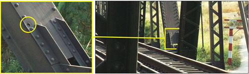
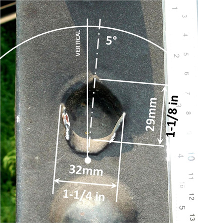
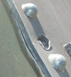
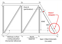
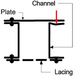
This is the second of three definite shell holes. A projectile fired from a northerly direction perforated a 10mm (3/8 in) thick structural steel plate and then penetrated a 16mm (5/8 in) thick steel channel leg directly behind the plate in the west leg of the north portal frame of Span 1. The angle of the through-axis of the hole cannot be determined to any meaningful accuracy. The plate at Point F is analogous to the plate perforated at Point A; however Hole A was located in the middle of the width of the plate, without any backing member to support it, whereas Hole F is located near the edge of the plate, with support behind from the leg of a channel riveted to the plate. See the cross-section of the built-up bridge member here. The hole is approximately 340mm above railtop (0 reference elevation): Looking southwest near the base of chord U7L8 in Span 1:[F01]
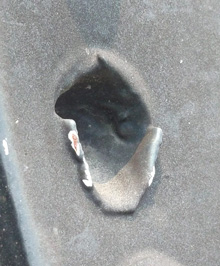
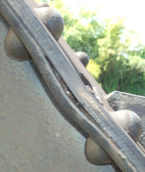
Looking SSE at Point F, camera is approximately perpendicular to steel plate:
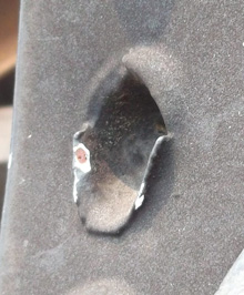
Macro views of Point F:
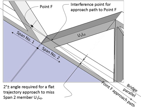
As with the hole at Point A, this hole has axes a bit tilted; however the (slightly) longer axis here is (nearly) horizontal with the shorter axis (nearly) vertical --- the opposite of Point A. The reason for this cannot be determined. The clean symmetry suggests that the projectile hit the target plate on a line approximately parallel to the longitudinal axis of the truss (in contrast to the teardrop shape of Hole A). While the bottom of the depression appears smoothly "cupped", this is probably exaggerated by paint having pooled during nearly 70 years of maintenance.[F03a] The impact point displays characteristics associated with edge effect as discussed before. In the side view (above) of Point F, the projectile can be seen to have perforated the 10mm (3/8 in) plate and somewhat bowed the plate, and then to have only penetrated the 16 mm (5/8 in) thick channel leg, causing it to distort to a greater extent than the plate; here the projectile's remaining kinetic energy was absorbed by: • Channel leg deforming (dishing) A key point: the projectile did not penetrate the total 25.7mm (1 in) thickness of structural steel; ie, the thickness of steel exceeded the ballistic limit of the projectile.[F03b] Unfortunately, there appears to be no data published on the ballistic limits in structural steel for various sized and types of projectiles. It is assumed that the lesser axis dimension, 29mm, represents the maximum possible diameter of the projectile.[F03b1] Williams lists calibers of 27mm (Mauser), 25mm (general), and 23mm (VYa, ZU) before he comes to a caliber listed in standard military references: 20mm.[F03b2] So it would appear highly probable that the hole was produced by a 20mm shell. However, Hole F's lesser dimension, 29mm (1-1/16 in), does substantially exceed the suggested 20mm shell. It is assumed that the failure of the projectile to produce a clean perforation of the target plate caused the projectile to mushroom, forcing away adjacent target material made molten by the collision. Sufficient heat was generated in the structural members during the conversion from kinetic energy during the impact that large "lips" of target material not only formed, but also sagged while molten under the pull of gravity, producing the minor shrouded effect at the top of the hole, and the major tongue effect at the bottom of the hole.[F03e] The pronounced lipping is consistent with the H/d ratio, 25.7mm / 20mm, or 1.285, a value substantially higher than the 0.5 at Point A, where lipping is almost non-existent (see discussion, page 1) It is assumed that the projectile fragmented during impact with the resultant debris dispersing widely. However, that is only a guess: no scarring on adjacent surfaces is visible to verify that. It is quite possible that scavengers dug the projectile out of the hole. The hole is also peculiarly sheltered within the truss members: the approach path for the projectile could only have been approximately parallel to the major axis of the bridge: this in order to avoid the sloped portal member U1L0 in the adjacent Span 2. If the approach path had been a flat trajectory, it would have had at the least a horizontal angle with the bridge longitudinal axis of about 2°. That minimum angle requirement would have decreased as the vertical angle (the angle of attack) moved upwards. This is a schematic looking SSW and downward at the westerly junction of Spans 1 and 2:[F04]
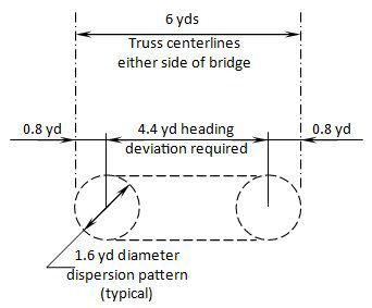
a = 914.7m x sin 2° = 31.9m (105 feet) At the breakaway point, say, 400 yards (365.9m) from the impact point, the shooter would need to have been east of the railroad track only:[F05] (365.9 / 914.7) x 31.9m = 12.8m (42 feet) Since the angle of the through-axis of Hole F cannot be established, the elevation of the shooter cannot be determined from Hole F. Possible sources for the hole at Point F Holes A and F are on opposite sides of a 6 yard (5.5m) wide (center-to-center) span, and separated by the 40m length of a span. Armorers assume a 4 mil dispersion pattern for a 20mm autocannon.[F05a] At the maximum range of 1000 yards (914.7m), the spread at the target would have been 4 yards (3.7m); at the breakaway point of 400 yards (365.9m), that spread would have been 1.6 yards (1.5m). At first glance, neither spread would have been sufficient to hit both Point A and Point F: However, dispersion patterns are a matter of probability, with 75% or 80% of the shots falling within that pattern, and with the distances of outliers undefined.[F06] Further, and more significantly, the pilot's tactic of tapping his rudder to circle his field of fire around his target could have easily broadened his field of fire to cover both points.[F07] To put both points within the standard 4 mil dispersion pattern by "tapping the rudder", the required deviation in aircraft heading would have been greater at the 400 yard (365.9m) breakaway point than at maximum range. In effect, the 400 yard distance provides the worst case scenario, so that is used below. At the breakaway point, the intrinsic dispersion pattern would have been stretched horizontally:[F08]
At 400 yards, one mil would equal 0.4 yard, so the required 4.4 yard deviation would require: 4.4 yd / 0.4 yd = 11 mils and 11 mils equals sin-1 = (11 / 1000) = 0.63° That is roughly half a degree which exceeded the accuracy available in the aircraft's compass and directional gyro.[F09] Hence it would have required an unmeasurably small change in aircraft heading. On this basis, then, it is concluded that the projectiles causing the damage at Points A and F could have been caused during a single strafing run on a train entering the superstructure of the bridge.
|
F01.^ Left photo extracted from DSCF1717 of 02 Feb 2014 and right photo extracted from DSCF1885 of 13 Feb 2014. Annotations by author using Microsoft Publisher. As with Hole No. 1, the same portal frame detail applies; projectile path through section is shown as red arrow:
(adapted from Bridge Inspector's Reference Manual (Washington: National Highway Institute, 2006) Fig 8.1.6, p 8.1.6, by author using Microsoft Publisher) F01a.^ Extract from DSCF2045.jpg of 17 Mar 2014. Annotations by author using Microsoft Publisher.
F02.^ Extract from DSCF2091.jpg of 03 Apr 2014. This photo is in focus: note clarity of breaks in paint; most detail is apparently softened by the accumulation of 70 years of paint maintenance. F03.^ Extract from DSCF2092.jpg of 03 Apr 2014. Comments in F02 above apply here.
F03Á.^ Looking SSW at base of northerly west portal frame for Truss No. 2, extract from DSCF2432.jpg of 02 Oct 2014. F03Ɓ.^ Looking WSW at base of northerly west portal frame for Truss No. 2, extract from DSCF2430.jpg of 02 Oct 2014.
F03a.^ The appearance of cupping may be a function of paint (from nearly 70 years of maintenance) pooling in the depression; this conclusion per vikingBerserker comment in ww2aircraft.net, 1815 03 Mar 2014. F03b.^ Definition per Børvik, Tore, ibid, Synopsis, p 11. F03b1.^ Christopher Perrien email of 0400 03 Apr 2014 clarified that in the case of an oval hole, only the smaller dimension of the hole was meaningful. F03b2.^ Williams, Anthony, Basic Ballistics, Table: "Bullet diameter / Cartridge designation". Ammunition Inspection Guide, TM 9-1904 (Washington: War Department, 1944). Standard military references: Barker, AJ, Japanese Army Handbook 1939-1945 (New York: Hippocrene, 1979). Isby, D, intro, and J Ethell, afterword, Handbook on Japanese Military Forces (Baton Rouge: Louisiana State University Press, 1991). F03e.^ For example, "lips" spread wider than the projectile, per Teng, et al, "Protection performance of double-layered metal shields against projectile impact", Jl of Mechanics of Materials and Structures, (2:7) (Sep 2007). Because the underlying plate was not perforated and the involvement of an edge effect, three illustrations, taken in combination, may best describe the situation at Hole F: Fig 16 (b), p 1322; Fig 19 (a), p 1324; and Fig 20 (a), p 1325. F04.^ Sketch by author using Trimble SketchUp. Annotations with Microsoft Publisher. F04a.^ LWD in Post #2 on Axis History Forum "Aircraft guns and bullet behavior" 04 Mar 2014, 15:22. Military Handbook Survivability, vol 2, Aircraft, Non-nuclear Airframe [MIL-HDBK 336-2] (Washington: DOD 1983), §5.5.3.1c, p 5‑98: "Impact with shielding often tumbles and distorts the penetrator projectile. . . ." F05.^ Wikipedia: Angular mil and Skinny triangle. F05a.^Manual for Fighter Gun Harmonization, ibid, "Fighter Harmonization Charts", P-38, p 31. F06.^ Air to Air Gunnery - Theory and Application: A typical gun dispersion results in about 80% of the rounds being grouped in a five-foot diameter circle at a range of 1000 feet. Ie: 80% inside a 5 mil cone. It's the 75% dispersion cone (75% of the bullet go through this cone) which is generally used because it prevents the weird magic bullet effect which could have an adverse effect on the 100% dispersion. Ie, if 5 mils covers 80%; then a smaller mil number would cover 75%. F07.^ 13th Bomb Squadron website Combat Tactics: Strafing (Area). F08.^ Sketch by author using Microsoft Publisher. F09.^ See Pilot's Flight Operating Instructions for Army Models P-38H Series, P‑38J‑5 and F‑5B‑1 (Chicago: Marshall‑White, 1943), Fig 7‑Instrument Panel, p 8. While not specifically applicable to P-38 instrumentation, this is generically applicable: Installation Manual and Operating Instructions: 3300 Series Directional Gyro (Wichita: Mid-Continent Instruments and Avionics, 2007), p 5: The dial has five-degree graduations with numerals every thirty degrees. Every ninety degrees is a cardinal reference letter (N, E, S, W).
|