| N 18°32.300 E 99°03.000 |
Ban San Khayom Bridge (Th: สะพานบานสันกะยบม / Jp: バンサンカヨム橋) Page 9 of 11 |
Railroad Sta |
| Text | Notes | ||||||||||||||||||||||||
|
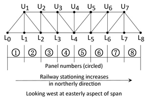
Supplemental Information: the structure To better identify specific truss members, ie, chords, and panels, this naming standard is used:
For record purposes: no manufacturer's plate or plaque was found on the bridge. The steel bridge was erected some time prior to the formal opening of the Northern Line on 01 Jan 1922. It replaced an earlier wooden structure erected to connect temporarily to Chiang Mai on 01 May 1920. Delivery from European fabricators for various steel structures on the line had been delayed, probably due to World War I.[N00a]
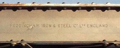
Since the various instances of damage noted all occurred on steel structural members, those members are here examined in more detail: All three holes involve built-up structural members using steel channel carrying the mark "Frodingham Iron and Steel Co, Ltd, England":[N01]
Frodingham Iron & Steel, North Lincolnshire, England, bought Appleby Steel in 1912 (or vice versa) and the company changed its name to Appleby-Frodingham Iron & Steel. The name "Appleby-Frodingham" appears on a Bailey bridge section in the old iron bridge at Pai, which would suggest that the structural members for this bridge in omitting "Appleby" were manufactured before 1912-1913. However, a commercial building recorded as constructed in 1933 has steel marked as on this San Khayom bridge, ie, with the name, Appleby, omitted. Hence, the omission would appear to be irrelevant for dating its manufacture. The channel apparently conforms to specifications unique to Frodingham and not to any steel manufacturer's standard in the US. As a result, the channel was measured in place; the flange is tapered and its thickness is therefore estimated. Dimensions of the Frodingham channel are:[N02]
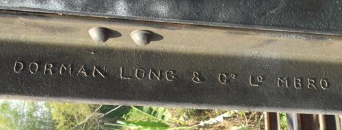
While the Frodingham name is displayed on the most prominent structural members, more members, specifically steel angle, carry the mark, "Dorman Long & Co Ld Mbro":[N03]
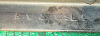
Dorman Long & Co, Ltd, Middlesbrough, in northern England, was a steel maker in Cleveland, northern England. Not long after supplying structural shapes for this bridge, it came to be noted for its specialization in bridge building, starting with the Omburman Bridge in Sudan in 1926. The plant was nationalized in 1967.[N04] A very few steel angles carry the identification, BV&Co, Ld:[N05]
The abbreviation was for Bolckow and Vaughan, partners who founded what eventually became a steel company, which, in 1929 --- subsequent to the manufacture of this bridge, failed financially, and ironically was taken over by the Dorman Long Company discussed just above.[N06] As clarification, it should be noted that Holes A and F are in structural steel plates in the built-up members; those plates display no maker's mark. That the plate is unidentified appears to have been standard practice. Hole G is in a channel labeled "Frodingham Iron and & Steel Co Ltd England". The identities of the companies that designed, fabricated, and erected the San Khayom bridge are not currently available: with Dorman Long & Co's later reputation noted above, it is conceivable that the company was involved.
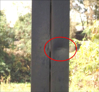
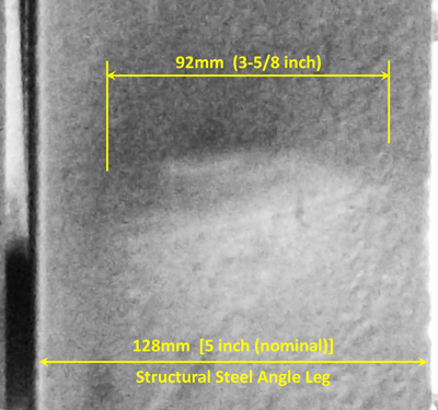
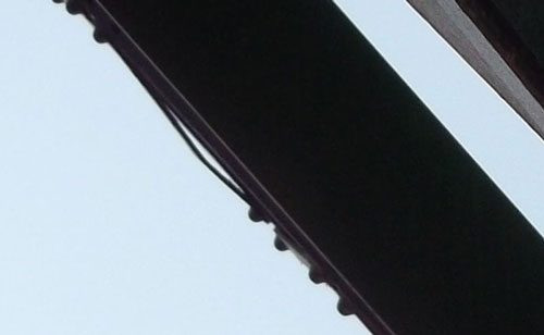
This damage was originally presumed to be a ricochet; however, on review, that seems improbable. It appears to be two simple longitudinal indentations that might have been fabrication blemishes, or the result of something falling from a passing train hitting the member at speed. The mark is 1560mm above railtop (0 reference elevation):
The detail is almost indiscernible except shortly before noon, sun-time, when the position of the sun maximizes the shadow of the mark:[E02]
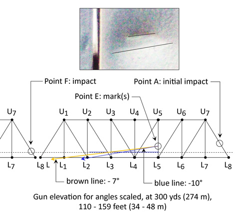
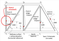
With the assumption that this was a ricochet mark, an earlier speculation saw a projectile glancing off Point E to impact at Point F. The diagram above demonstrates this would have been impossible since the projectile's course would have taken it well below the elevation of Point F. Further, the sheltered position of Point F also makes this speculation impossible, for the projectile would have had to pass through Span 2 portal member U1L0 to reach Point F. No evidence has been found that a projectile, if it did ricochet at Point E, impacted any transverse floor steel support members downstream of Point E. However access to those particular members is difficult as is and is made more so by heavy sheet metal guards hung over the cross members outside each rail, so such an impact point might exist, but would be currently obscured. The ricocheting shell might also have hit one or more hardwood sleepers (rail ties). These would have been long ago replaced: the current ties all display the number 47 which is assumed to mean the Thai year 2547, which was 2004 in the Western calendar. As noted in the last sketch above, probable gun elevations (altitudes) ranged between 34 - 48m (110-159 ft). Taking into account the vagaries of flight under combat conditions, this might be considered roughly consistent with the 100 foot altitude at 400 yards noted on page 1.
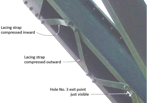
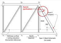
Two deformed lacing straps on the underside of a built-up structural member (Span 1: U7L8) are probably unrelated to the shell that caused the hole at Point G. The two members are not directly opposite the impact point (hole); there are similar details on this bridge and numerous instances of equally bent lacing straps on the similarly designed Ban Tha Lo Bridge, over the Nam Mae Kuang, about 6 km north, which appears not to have been damaged at all during the war:[N07]
A key point about the bent lacing straps is that the 12-inch (nominal) structural channels to which they are attached all run true --- they display no distortion, which strongly implies that the bending of the lacing straps was intentional, most probably to line up rivet holes punched slightly off dimension, due to shop fabrication error.
|
N00.^ UXLX format is standard for detailing truss bridges. Drawing by author using Microsoft Publisher.
N00a.^ Wisarut Bholsithi email of 2224 hrs 03 Mar 2014
N01.^ The name is directly above Point G; extract from DSCF1719.jpg of 02 Feb 2014.
N02.^ The dimensions do not match those in any American steel manuals cataloguing US steel manufacturers' products. See corroborating comment at Eng-Tips Forums 1930s British Steel Sections.
N03.^ Extract from DSCF1954.jpg of 26 Feb 2014; (enhanced).
N04.^ Dorman Long in Wikipedia. N05.^ Extract from DSCF1956.jpg of 26 Feb 2014 (enhanced).
N06.^ Wikipedia: Barrow Steel;
Point E:
E01.^ Extract from DSCF1900.jpg of 18 Feb 2014.
E02.^ Extract from DSCF1903.jpg of 18 Feb 2014. View in rendered in black & white to eliminate possibly distracting false color resulting from enhancing the image. Annotations added with Microsoft Publisher by author.
E03.^ Sketch is not-to-scale, but approximately proportionally correct. Done by author using Microsoft Publisher. Photo: extract from DSCF1901.jpg of 18 Feb 2014; annotated by author using Microsoft Publisher. Gun elevations were calculated as:
General Area of Point G:
N07.^ Looking northwest at Hole G; extract from DSCF1807.jpg of 06 Feb 2014; strongly enhanced. The railway bridge spanning the Nam Mae Kuang is at N18°35.117 E00°01.296; with railway stationing 728+280. Thai Road No. 1102 parallels the track and provides access from the east; an unnumbered road parallels the track on the west. Its truss design appears to be the same as that for the San Khayom bridge; manufacturer of the structural steel angle for this second bridge does differ though: Capco-Fleet, England rather than Dorman Long & Co Mbro or BV&Co, Ld.
N08.^ Looking west at Hole G; extract from DSCF1806.jpg of 06 Feb 2014; strongly enhanced
N09-N14. (deleted).
|
||||||||||||||||||||||||