| N 18°32.300 E 99°03.000 |
Ban San Khayom Bridge (Th: สะพานบานสันกะยบม / Jp: バンサンカヨム橋) Page 2 of 11 |
Railroad Sta |
| Text | Notes | ||||||||
|
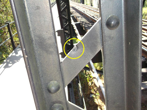
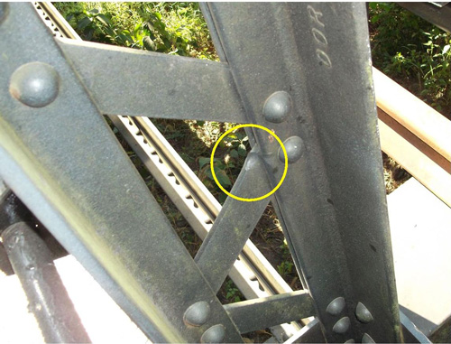
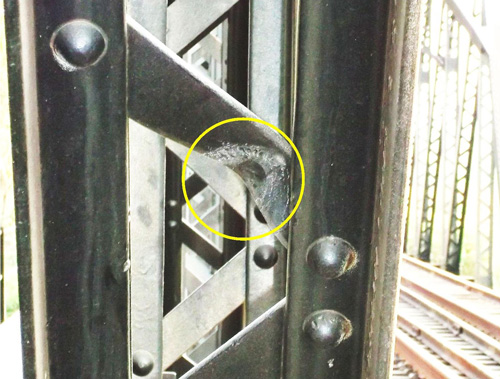
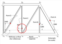
The mark is on a 10mm (3/8 in) thick structural steel lattice or lacing strap in vertical built-up chord U7L7, between Panels 7 and 8. Looking south at Point B impact:[B01]
The impact at Point B involves "edge effect", which is defined as:[B05] If a penetrator strikes close to the edge of a target, the target material will behave differently compared to a hit [far] from an edge. It is likely that the resulting penetration of the target will be higher than expected. A minimum distance from a free edge may be specified in terms of the number of penetrator diameters to minimise this effect during testing. . . . an edge effect appears [for example] when there is insufficient lateral confinement, which presumably allows the armour to "bulge" sideways more easily, likely presenting less resistance. The projectile would have arrived from Point A tumbling at an unknown rate. At Point B, the tumbling would appear to have put slightly less than half[B05a] the circular base of the projectile in forceful contact with the edge of a lattice strap, recording its impact as an indentation. With less than half the circular base in contact with the lattice strap, and the projectile already rotating, its off-center collision would have acted as a force to continue rotation of the projectile. It is unknown if the initial collision with the strap appreciably slowed the projectile's tumbling; nor is it known how much the off-center collision itself might have increased the rate of tumbling. In any case, a continuing rotation apparently carried the tumbling shell over the strap edge, the path of least resistance, with possible slippage, to continue on a slightly altered tumbling course to Point C.[B06]
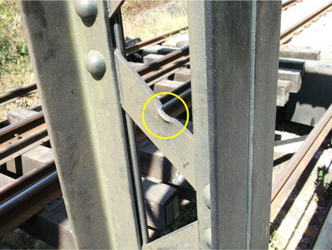
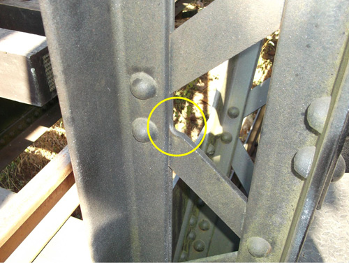
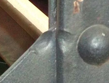
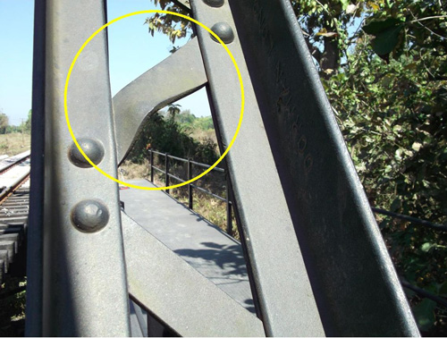
As with Point B, this mark is also on a 10mm (3/8 in) thick lacing strap; but it extends as well to an adjacent angle in the vertical chord, U6L6, of the truss between Panels 6 and 7. View of Point C impact, looking SSE and down:[C01]
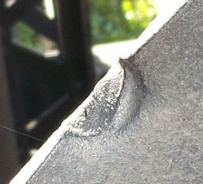
Discussion about damage at Point C It may not be clear from the photo of the "entry" point, but the two marks are indentations, not "bubbles". This is clear in the view of the "exit" point (right view above). The maximum indentation from the plane of the lattice strap at the "entry" point is 14mm (9/16 in). This would appear to be another example of "edge effect" --- here the ogive-shaped nose of the shell left its mark on the intersection of a lattice strap and an angle; the projectile hit close enough to the edges of the two steel members that they were both deformed; and that deformation was limited by the mutual support provided by the two members which were riveted together. The projectile struck at such an angle that the impact did not stop its tumbling, which carried it over Point C to continue towards Point D, albeit on a slightly altered course.
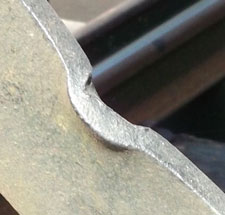
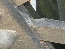
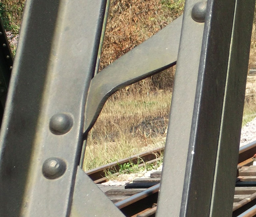
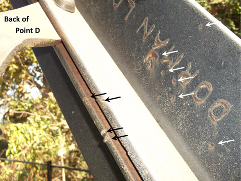
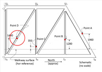
Again, as with Points B and C, the mark is primarily on a 10mm (3/8 in) thick structural steel lattice or lacing strap, but in lateral built-up chord U6L5 in Panel 6. Front view of Point D impact, looking SSE and level:[D01]
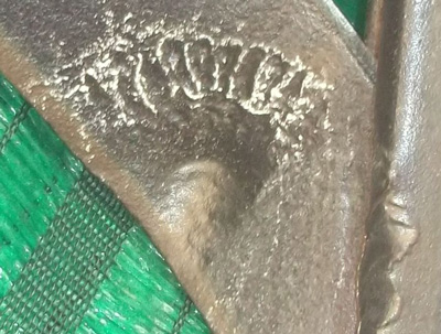
Closeup of the impact point, looking south and slightly up (chalk has been used to enhance markings; green behind is cloth to shield camera from the sun):[D04]
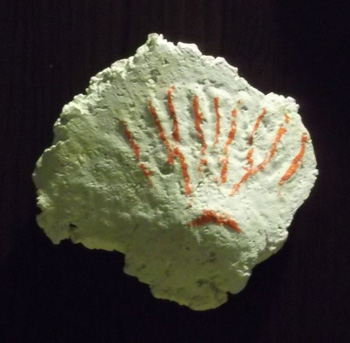
In the three previous collision, the projectile had lost kinetic energy: first in perforating Point A, and then in deforming lattice straps at Points B and C. In addition, each of those impacts would have added structural damage to the projectile. At Point D, the base of the tumbling shell hit a lattice strap near its center --- quite squarely, more so than at Points B and C so that there was less of an edge effect. As a result, the tumbling effect could not rotate the shell over Point D and further into the truss. Thus a much greater amount of kinetic energy had to be dissipated at this point with a dramatic deforming of the lattice strap. The rotational energy involved in the tumbling of the projectile and its counterclockwise direction, apparently turned into a skidding as evidenced by the clear elongated indentation of the base of the projectile on the lattice strap. The indentation of the lattice strap at Point D (37mm) is considerably greater than at Points B (13mm) and C (14mm). At the same time, the weakened shell appears to have fragmented, leaving radial scars around the indentation and more diffuse scars on the structural angle adjacent within the built-up member. The indentation caused by the base of the shell is most pronounced farthest from the unsupported edge of the strap; the indentation is circular and its diameter measures about 20mm. The scarring appears to radiate from the center of the main indentation.[D04b] On the angle leg at lower right appears to be what might be additional fragment scarring, though less ordered. Radial scarring from "two o'clock" to "five o'clock", although not visible in this photograph, seems to exist in lesser form in the plaster cast below (though that can't be brought out in a photo either). A plaster cast of Point D provides an alternate view of the radial scarring. The high points on the casting (the radial scarring and the projectile base) are "highlighted" in red (realize that these are actually indentations in the lacing bar):[D05]
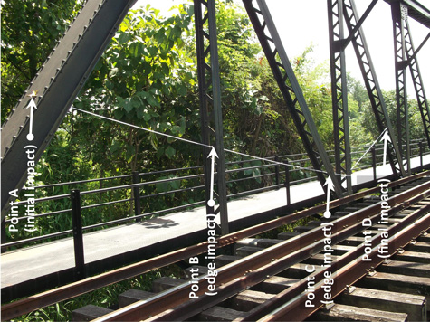
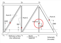
A review of the relationship of Points A, B, C, D The projectile entered the easterly truss of Span 2 at Point A. Downstream Points B, C, and D are all within the confines of the truss. A string line connecting the four found no interferences with the crisscrossing lacing or lattice straps between the points. No evidence of the projectile's movement beyond Point D was found:[D05a]
A conclusion to be drawn is that the four points, A through D, are directly related to the movement of one 20mm shell within and through the superstructure of the easterly truss of Span 2.
|
Point B:
B01.^ Extract from DSCF1770.jpg of 06 Feb 2014.
B02.^ Extract from DSCF1768.jpg of 06 Feb 2014.
B03.^ Extract from DSCF1770.jpg of 06 Feb 2014. B04.^ Extract from DSCF1768.jpg of 06 Feb 2014.
B05a.^ Recht, RF, and TW Ipson, Final Report: The Dynamics of Terminal Ballistics (Denver: Denver Research Institute, 1962), pp 68 ff: discussion of edge impact. R here would have been positive. B06.^ Behavior of both shell and target when a shell hits the edge or near the edge of a target appears to be a separate subfield in ballistics. The concept of "edge effect" was introduced by EwingGreg comment of 1639 11 Apr 2014 in Delphi Forum: Military Guns and Ammunition. Effect is discussed by Vanir Ausf B, 2335 17 Jul 2013, on Battlefront Forum: Combat Mission: Fortress Italy.
Point C:
C01.^ Extract from DSCF1782.jpg of 06 Feb 2014.
C02.^ Extract from DSCF1780.jpg of 06 Feb 2014.
C03.^ Extract from DSCF1780.jpg of 06 Feb 2014. C04.^ Extract from DSCF1790.jpg of 06 Feb 2014 (enhanced).
Point D:
D01.^ Extract from DSCF2019.jpg of 27 Feb 2014.
D02.^ Extract from DSCF1796.jpg of 06 Feb 2014.
D03.^ Extract from DSCF1784.jpg of 06 Feb 2014.
D04.^ Extract from DSCF1996.jpg of 27 Feb 2014.
D04a.^ DSCF1800.jpg, dated 06 Feb 2014.
D04b.^ The possibility of fragmentation was introduced by EwingGreg comment of 1639 11 Apr 2014 (5883.6) in Delphi Forum: Military Guns and Ammunition. Most ballistics literature deals with AP shells impacting hardened steel targets (BHN 250+), not structural steel (BHN 149); thus there is not much guidance available. HS.404 projectiles were "cold drawn steel" per Ammunition Inspection Guide, TM 9-1904 (Washington: War Department, 1944), pp 325, 328. D05.^ Extract of DSCF2389.jpg of 20 Jun 2014.
D05Ƌ.^ See discussion in International Ammunition Association Forum: islandee post of 1104 23 Mar 2014 and EOD post of 1136 23 Mar 2014.
D05a.^ DSCF2398.jpg of 03 Oct 2014, annotated by author with Microsoft Publisher. A practical note on stringing bullet paths: an earlier version of this view had a bright yellow, but very thin rope that didn't photograph well because it was too thin. This photo uses a much thicker rope and is much more visible. But a mechanical problem arose during stringing the holes: the thicker rope visibly sagged from its own weight and it took some considerable cinching to take out the sags.
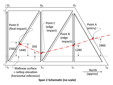
D06.^ Schematic looking west at north end of east truss in Span 2. Drawn by author with Microsoft Publisher.
|